
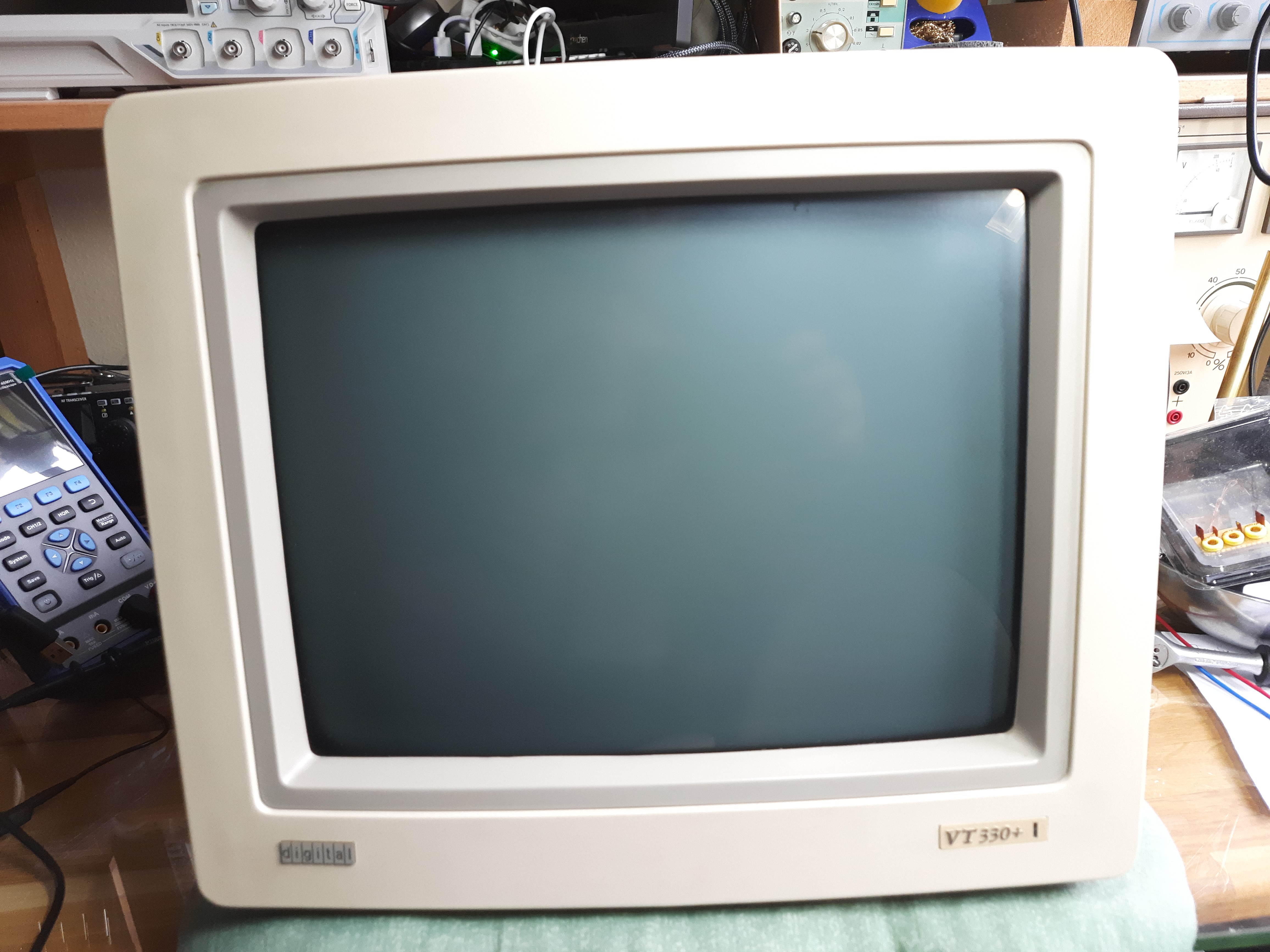
Digital DEC VT 330+ Terminal
DEC VT 330+ is a successor of VT330. My device has latest date codes from week 28 in 1990, so it is about 1990 or 1991. The electronics differs from the VT330, the digital logic part is build on a single PCB only. While older VT330 were built on two boards.
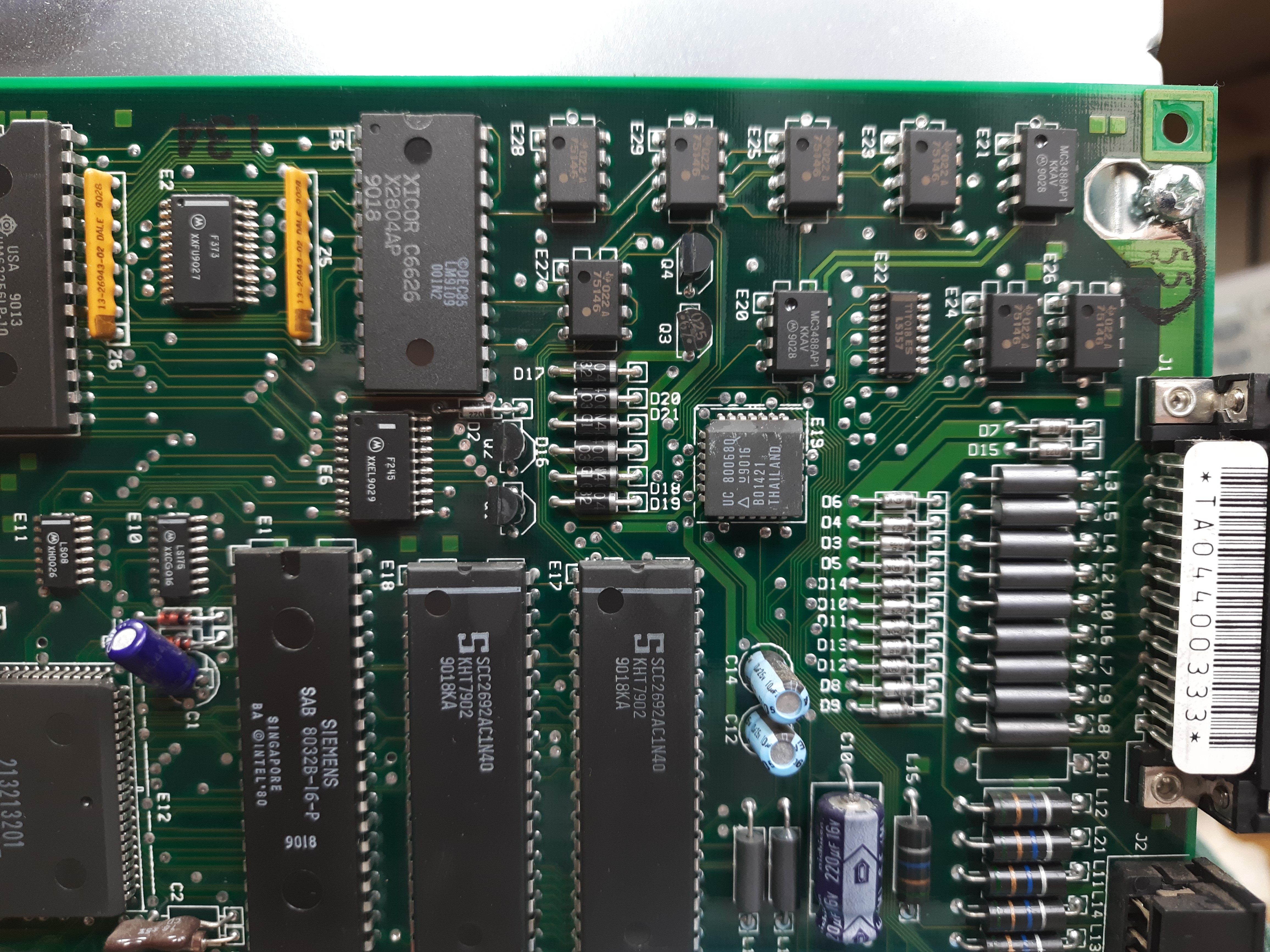
This newer board has an Intel 8032 8-Bit CPU, 2x128 KByte EPROMS (27C010), 2xHM62256 2x32KByte RAM. The microcontroller has two companion chips SCC2692AC1N40, these are dual asynchronous receiver/transmitters. There is also a gate array TC110G32AT with about 13.000 gates, usable up to 150Mhz. The 8032 seems to run with a 16Mhz clock.
Digital board:
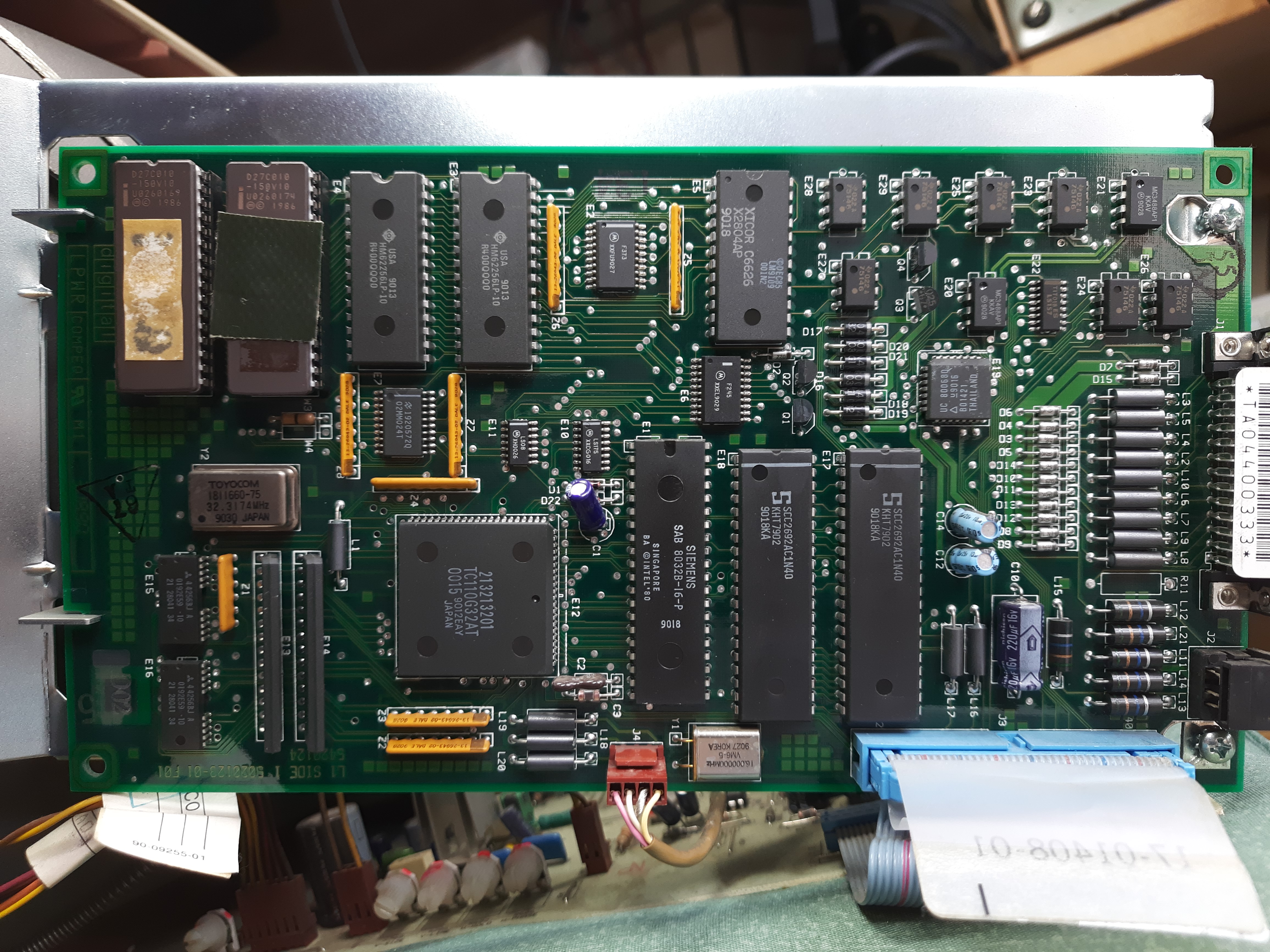
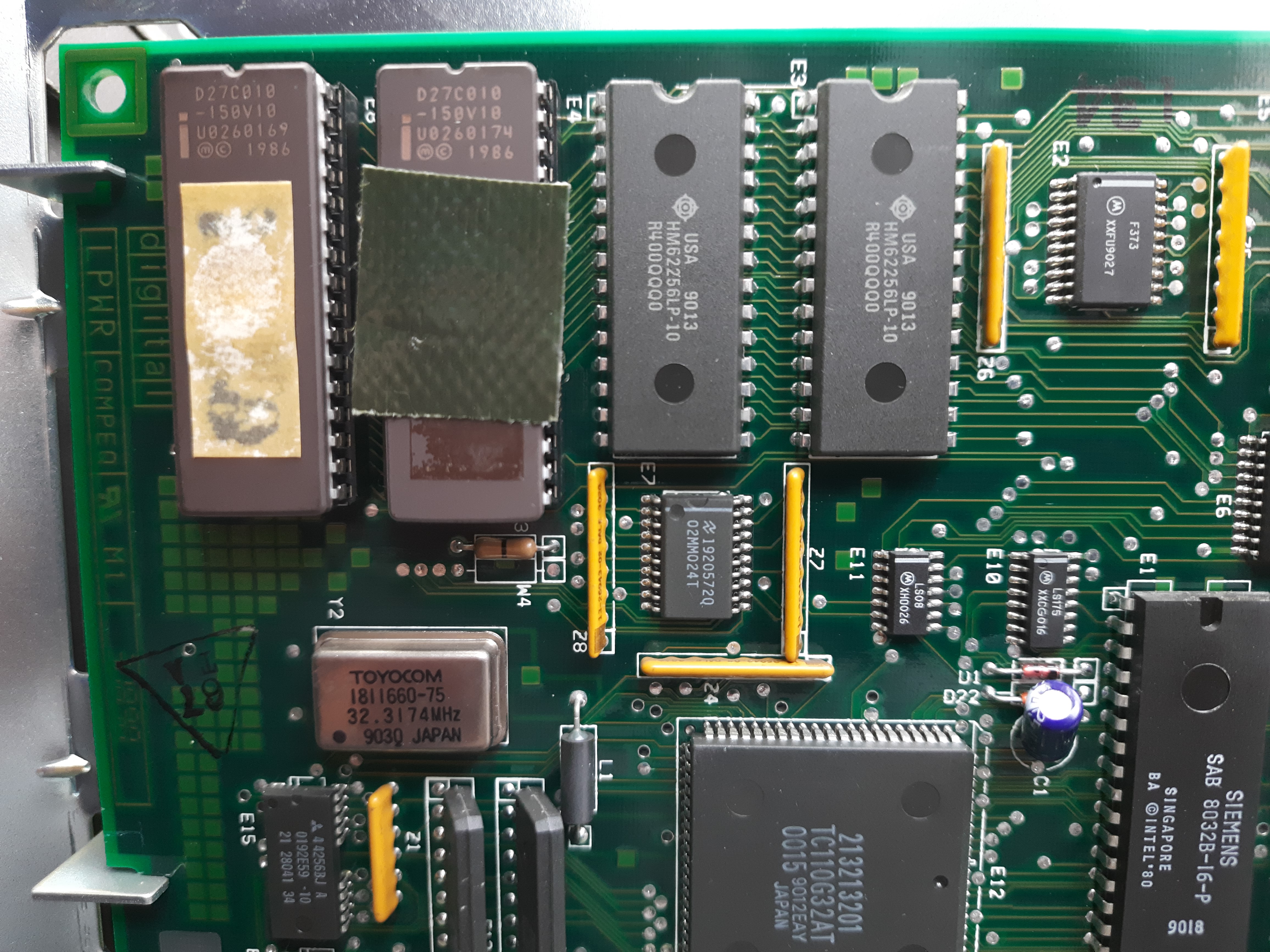
EPROMs and RAM chips. On one of the EPROMs, the sticker had fallen of and
I could not find it inside of the housing.
So I added a piece of dark sticky tape to replace it. I copied the EPROMs
later and found that both still have valid content.
8032 CPU and a multi-pin gate array:
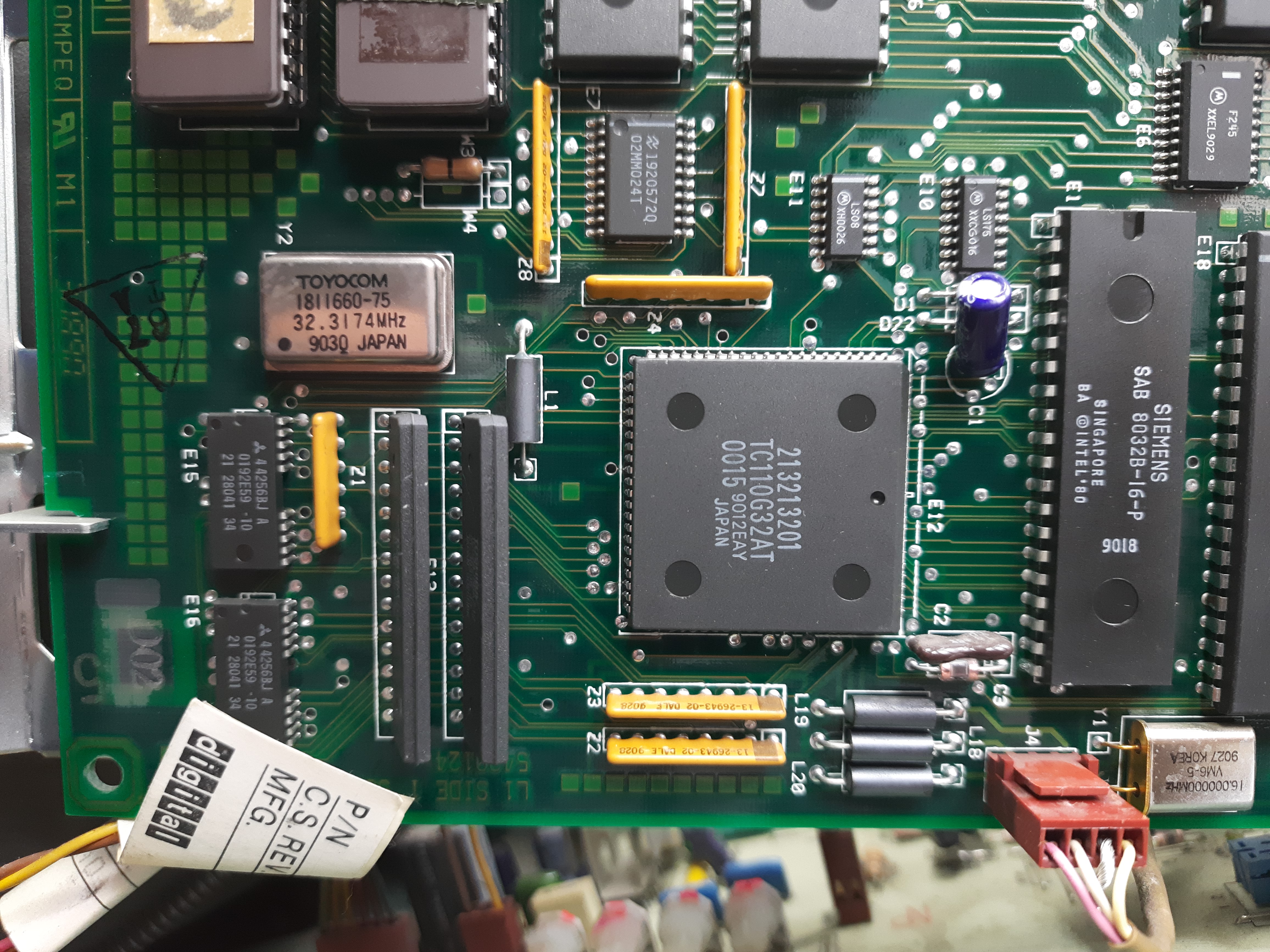
8032 CPU and … RAM?
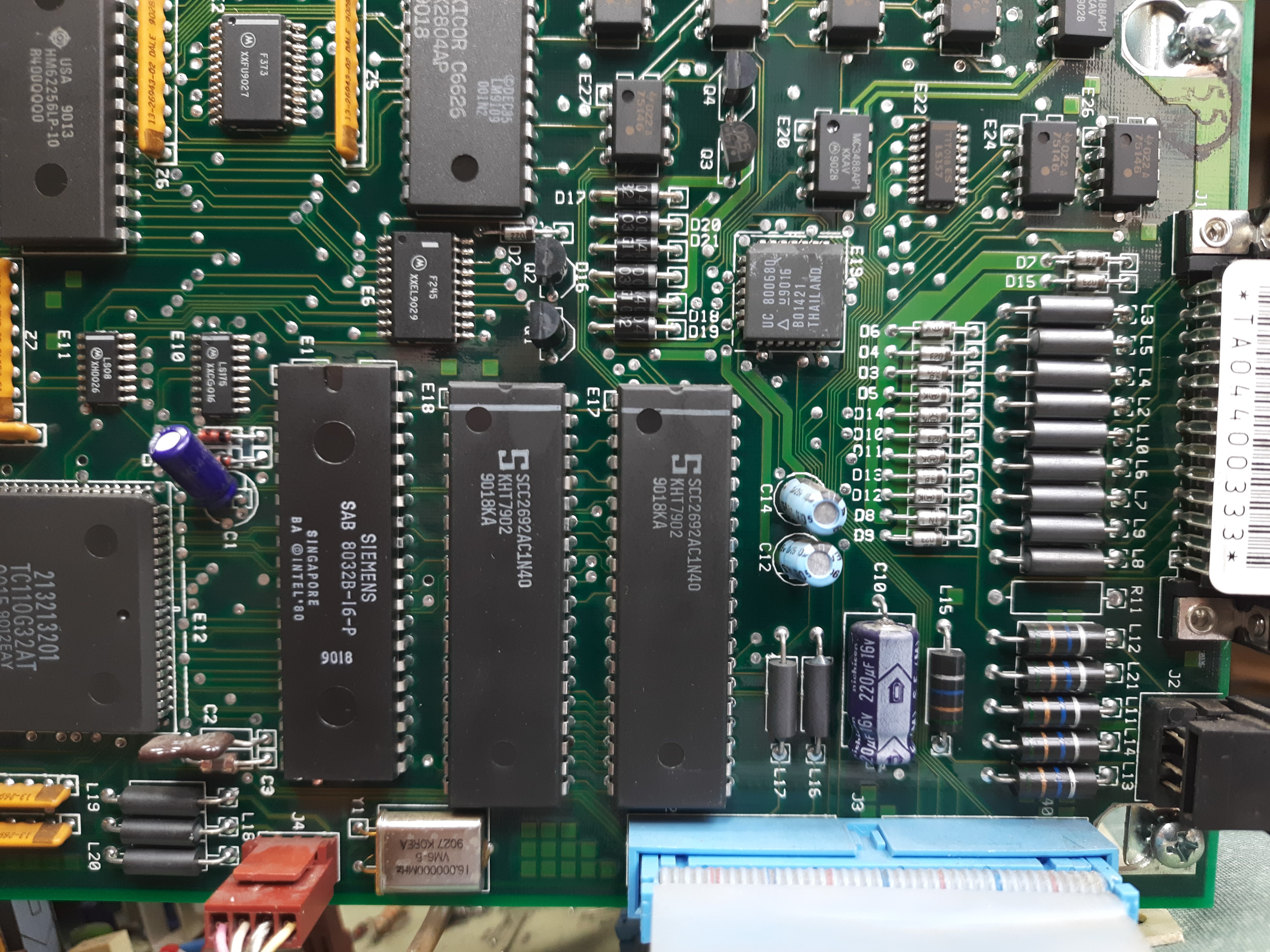
Upper left area of PCB:
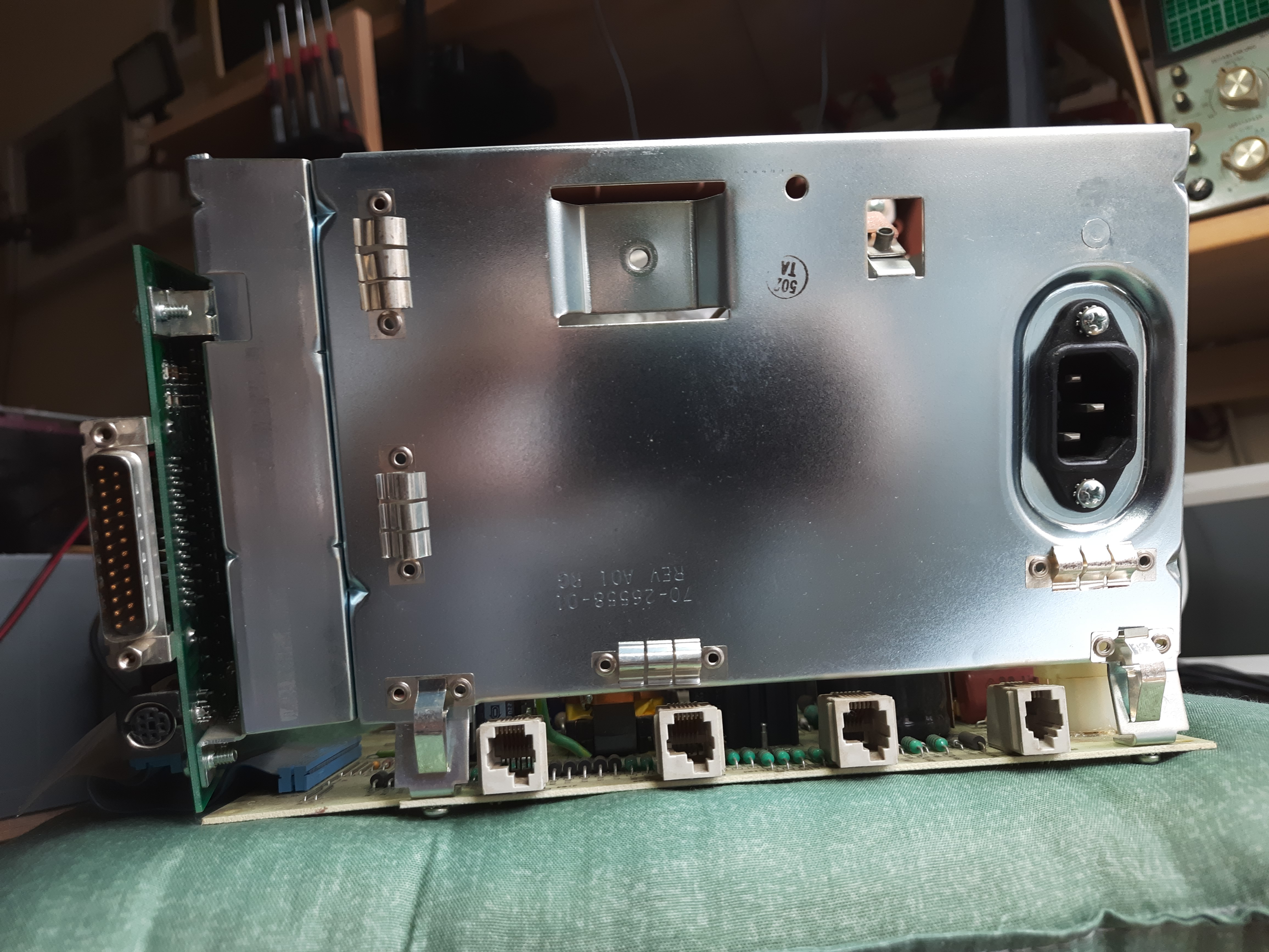
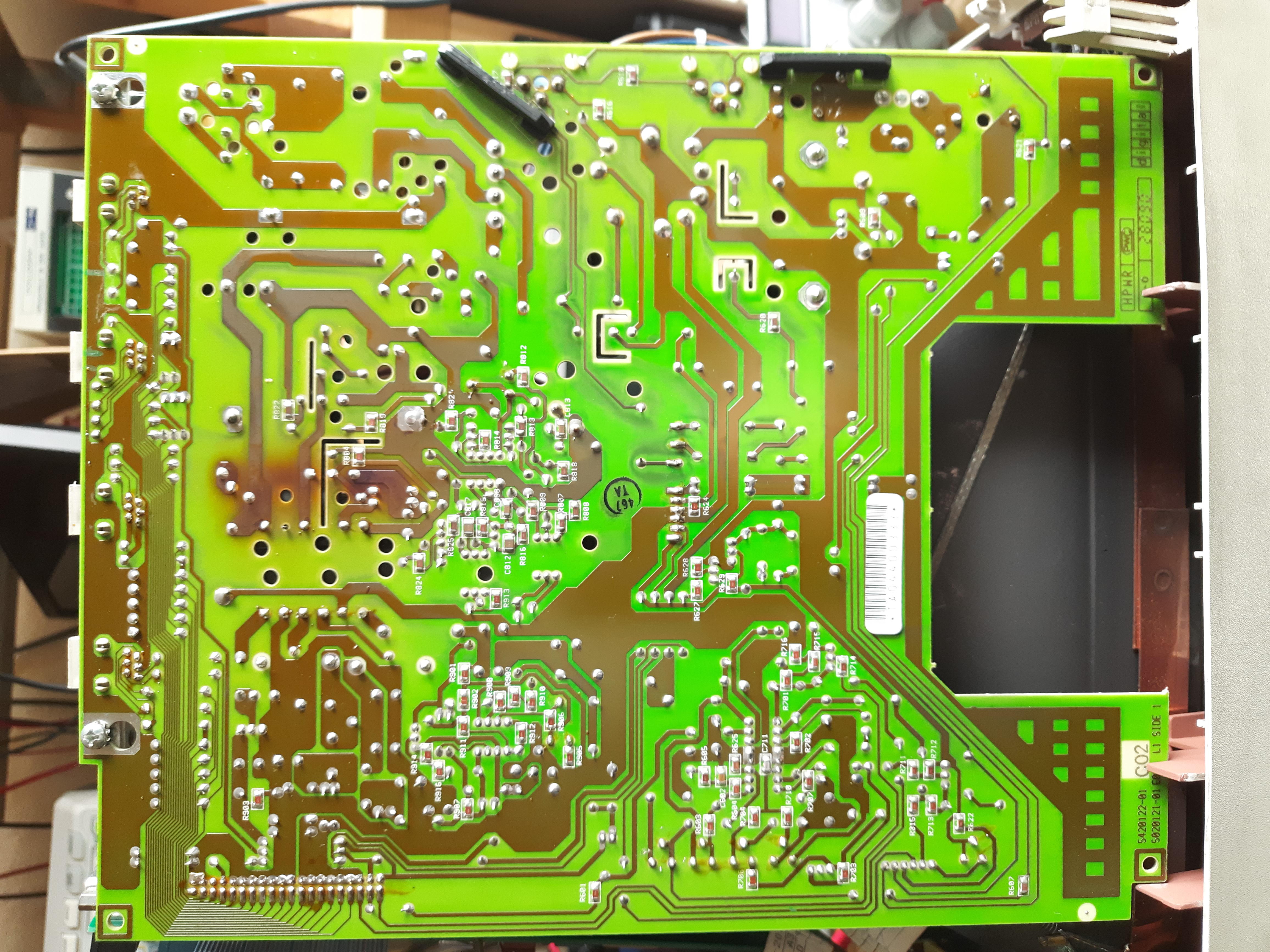
Back side with all connectors:
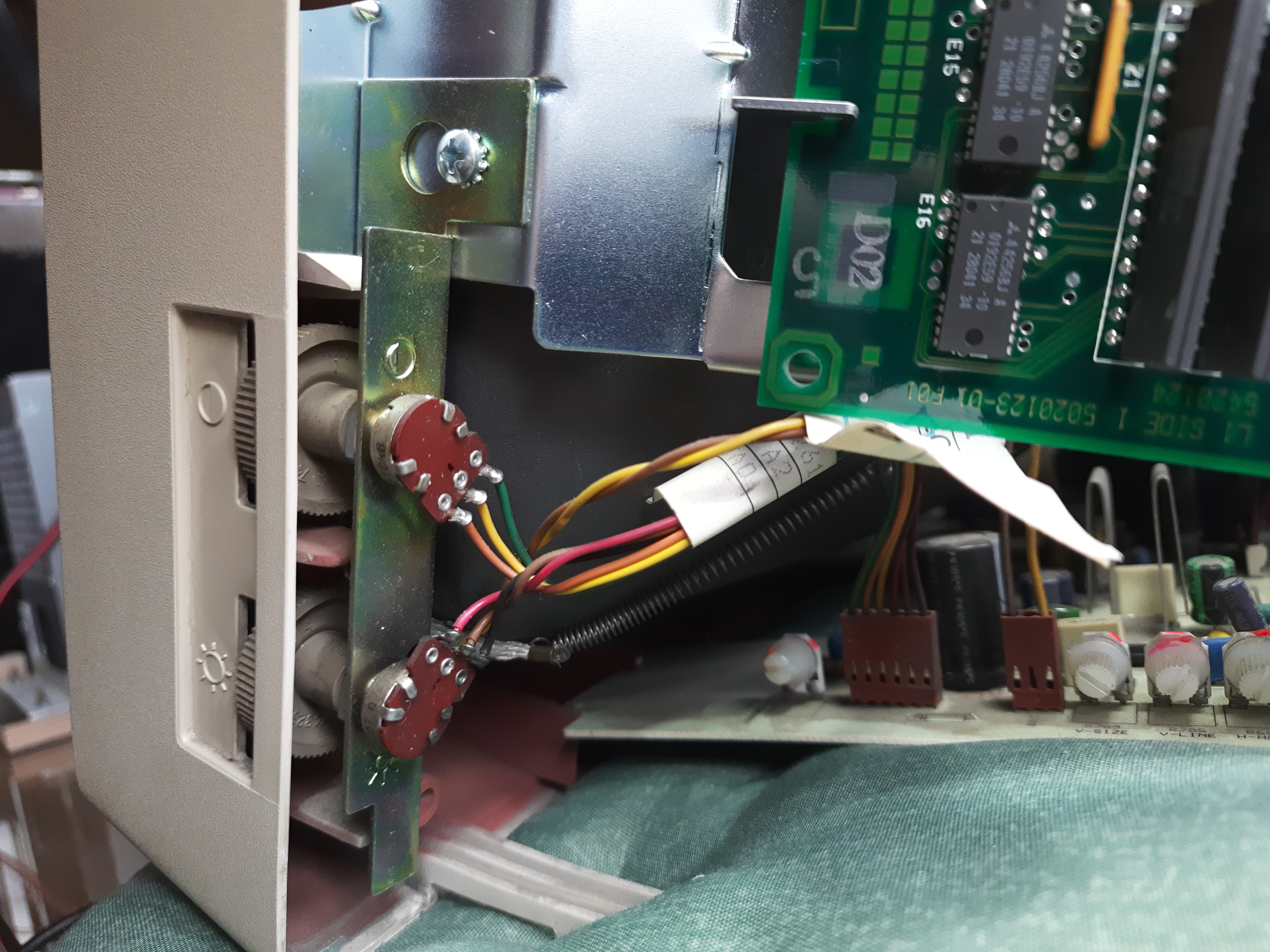
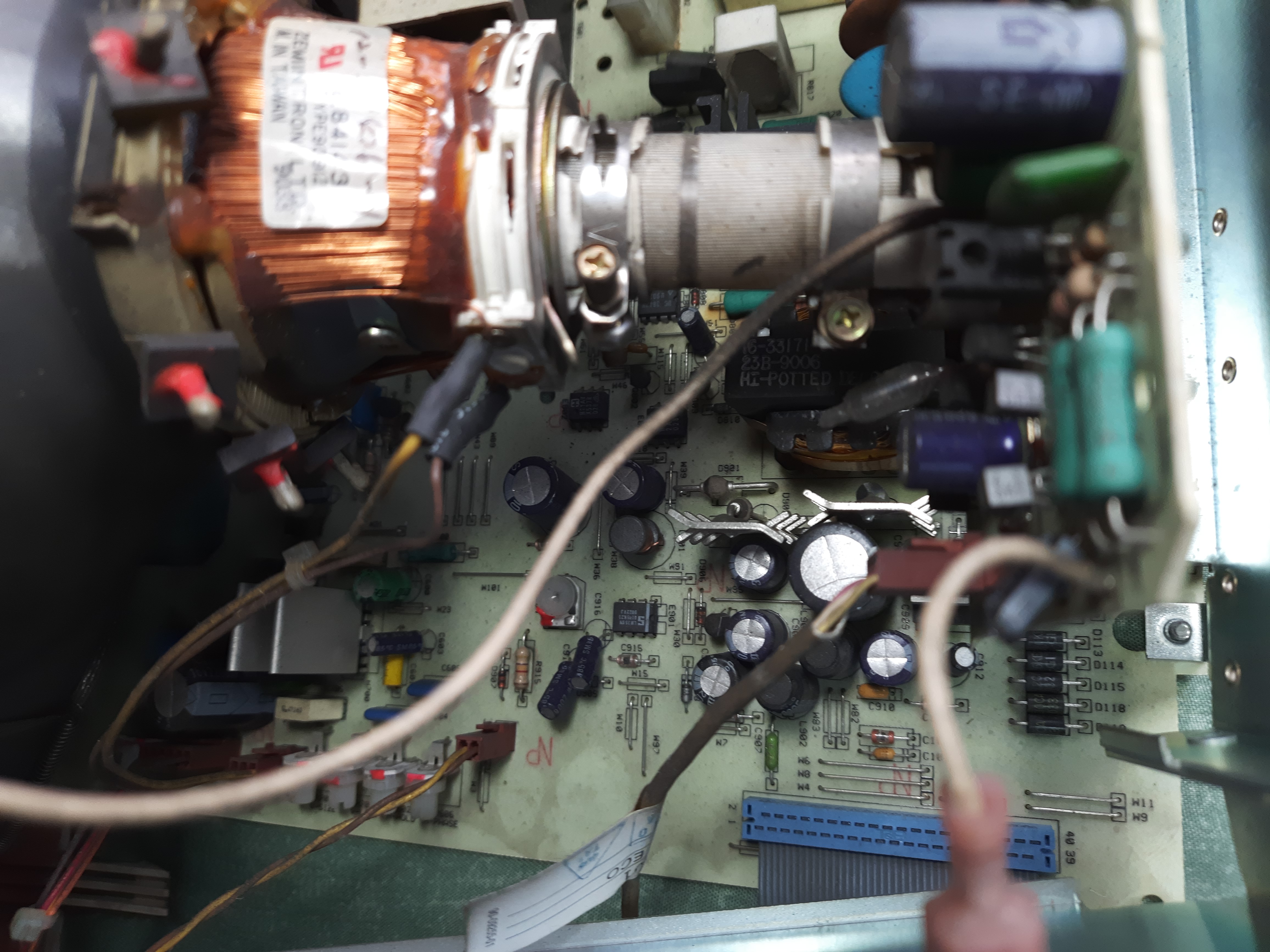
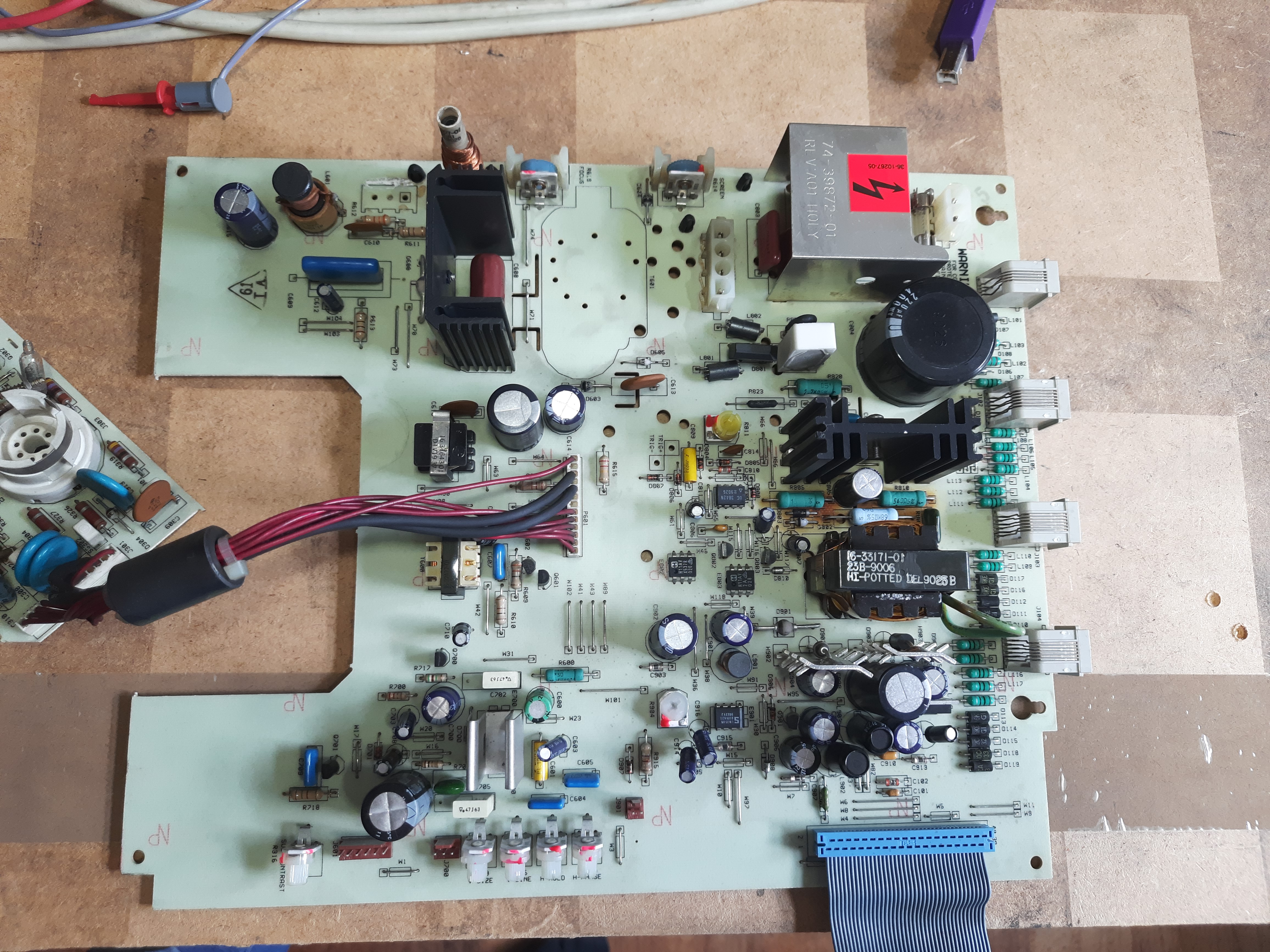
Video board left side:
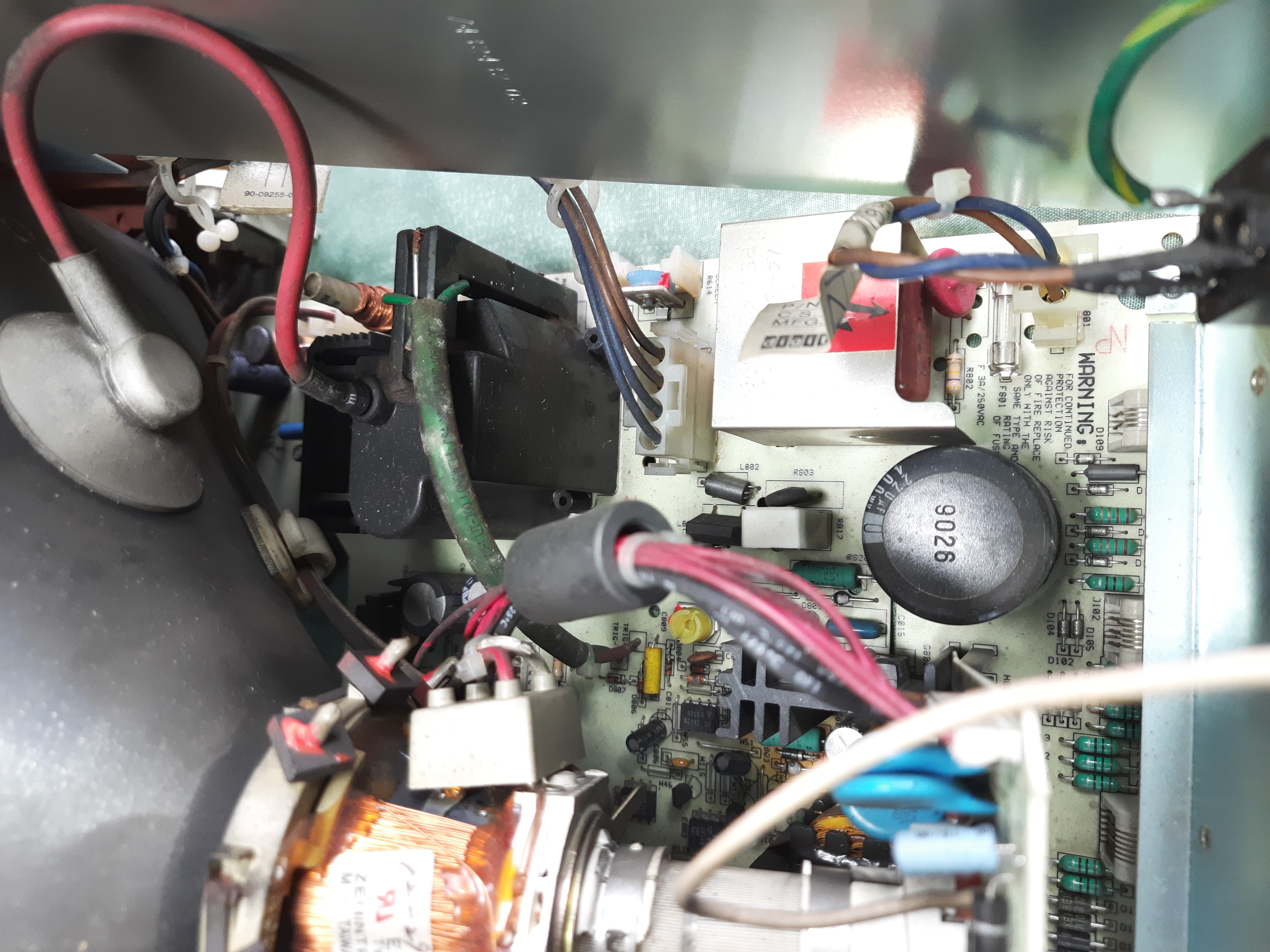
Video board right side with HV section:
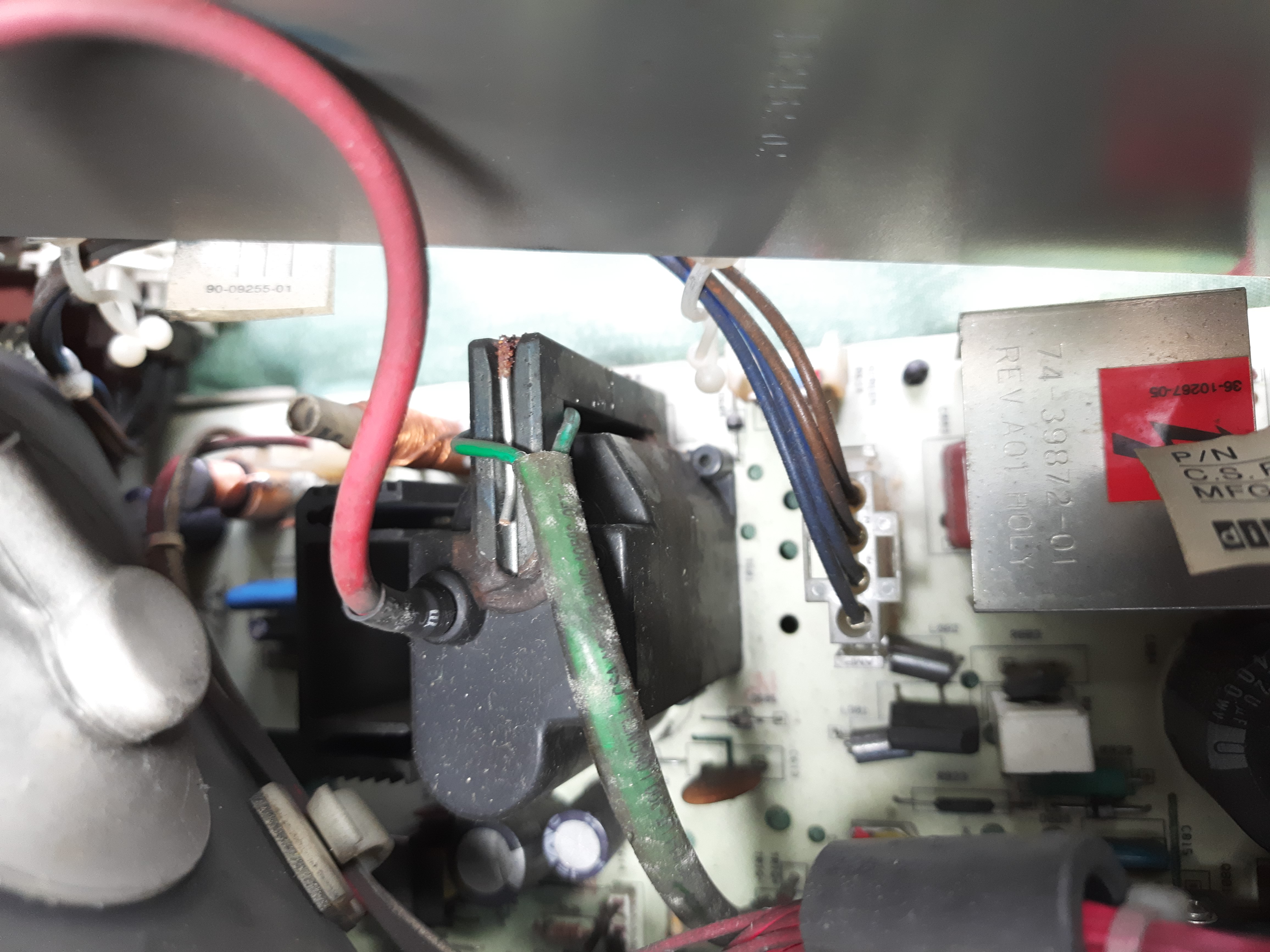
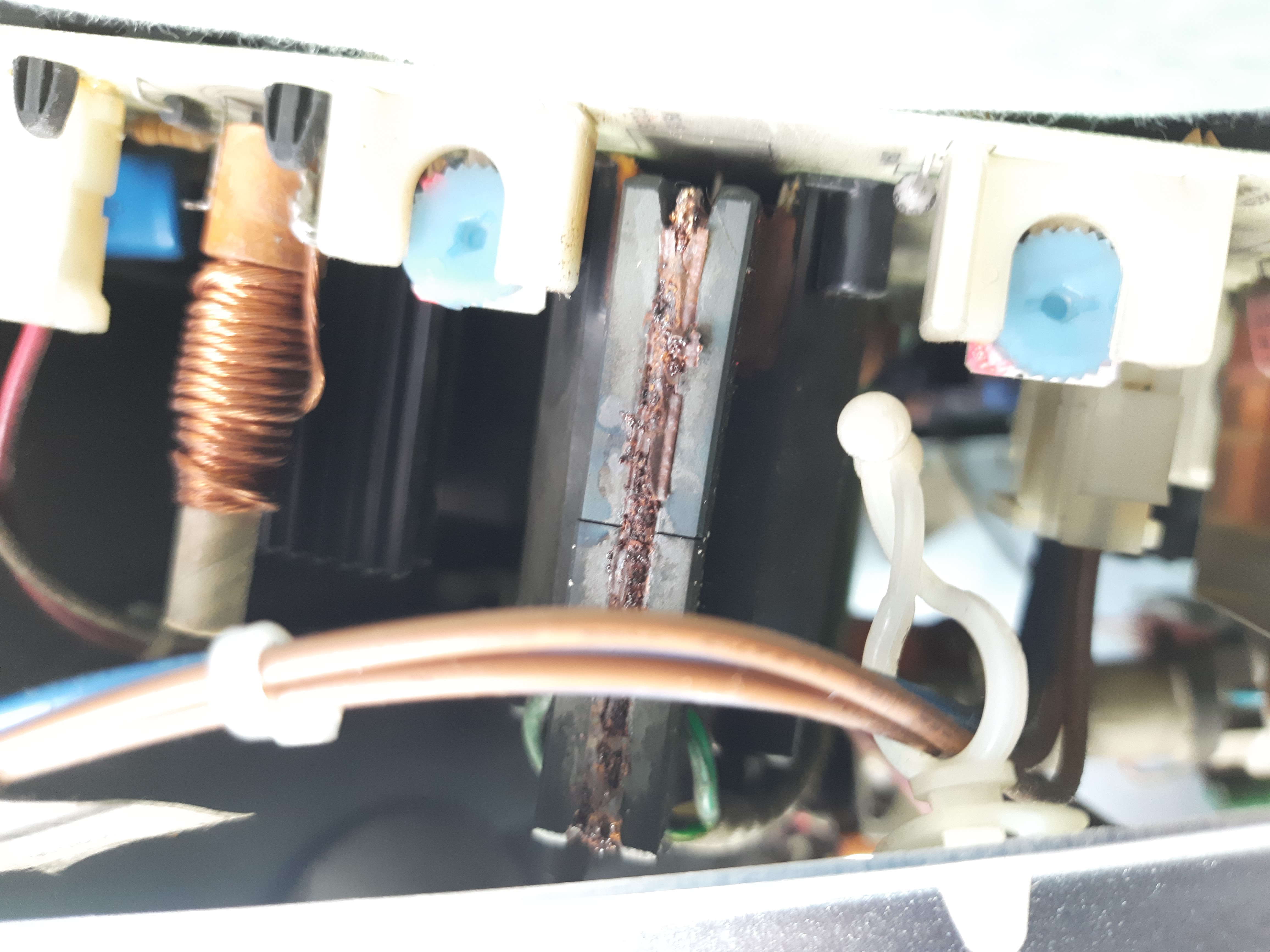
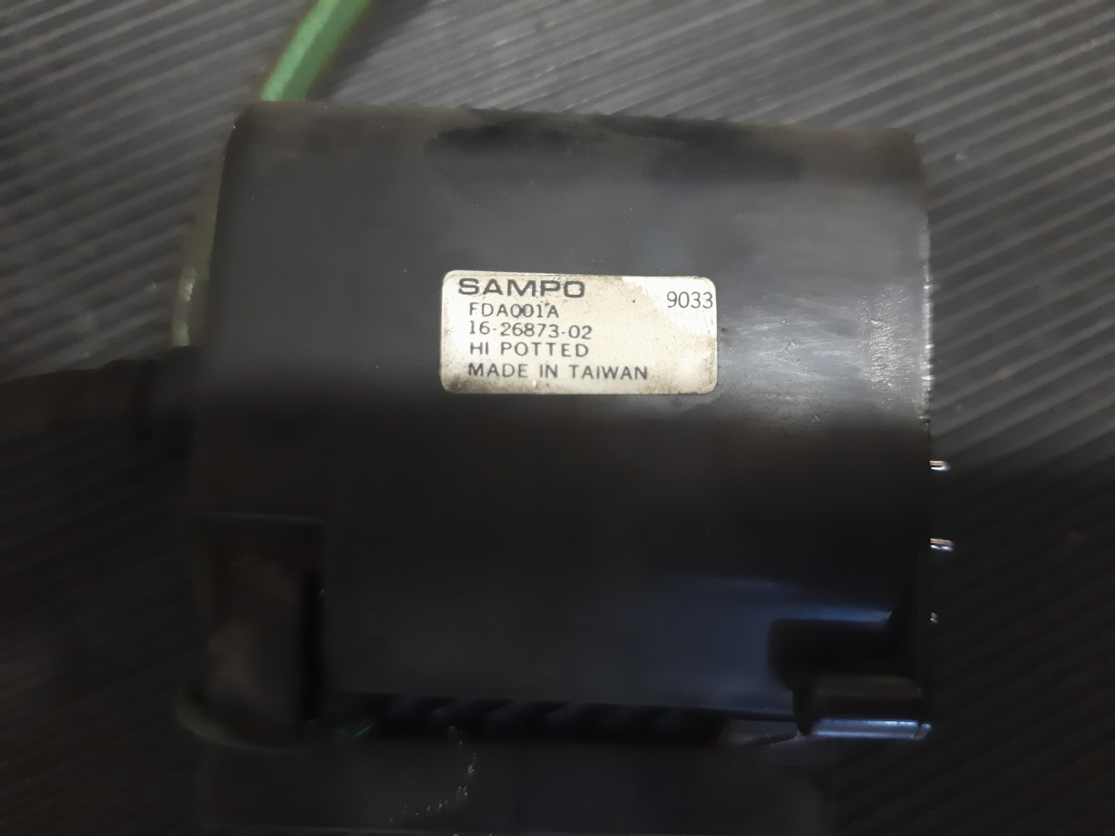
Flyback transformer detail. This is supposed to be defect.
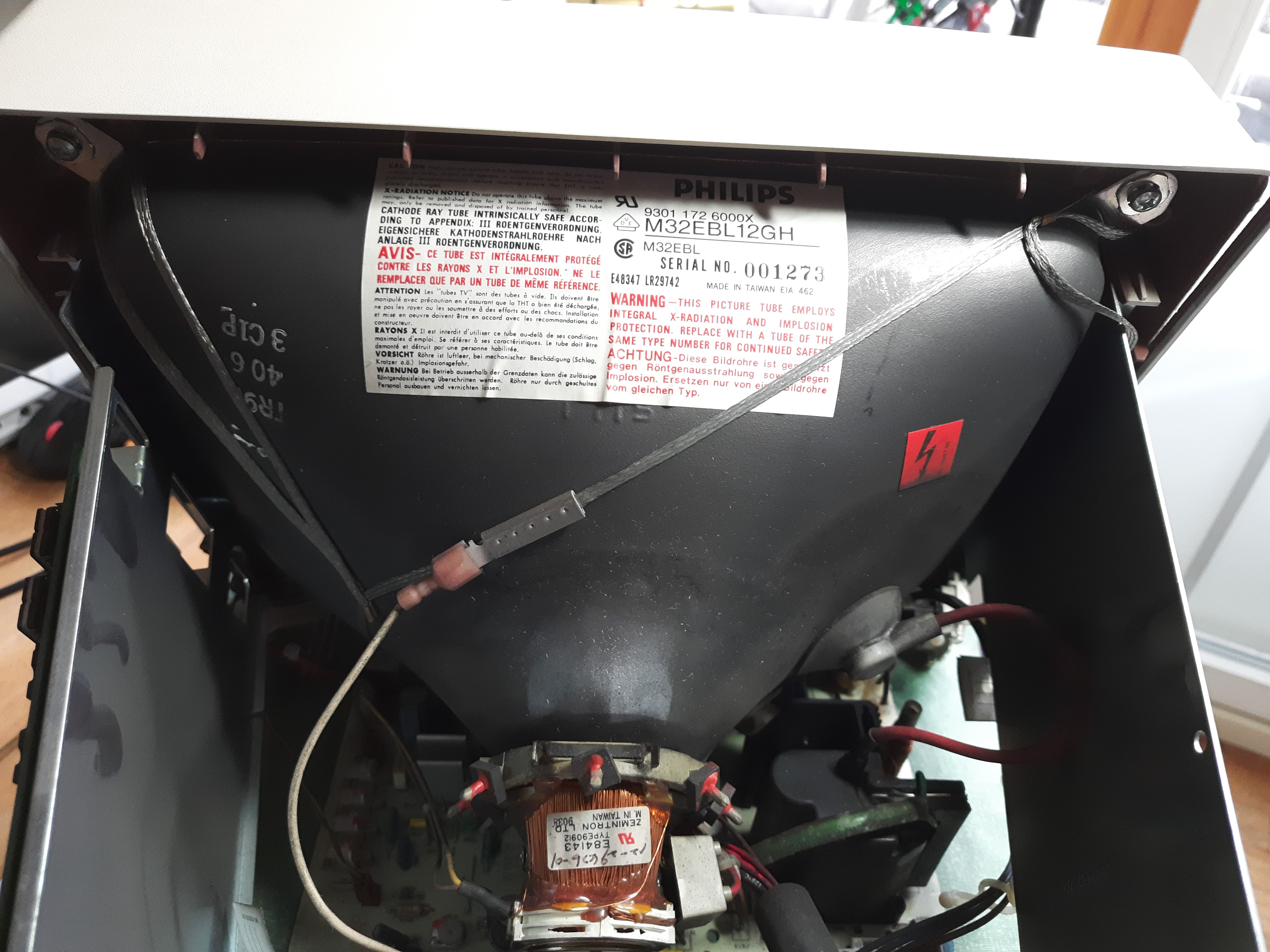
Display tube:
Video PCB detail:
Repair try
When switching the terminal on, the green display LED blinks, nothing more happens. There was a silent clicking noise, with about 1/4Hz frequency.
Note that VT330+ is different from VT330. Schematics and parts differ. There is no schematics for VT330+ on the internet. I “found” the service manual, which was believed to be not online. Info on that search for the service guide see here: https://forum.vcfed.org/index.php?threads/dec-vt330-service-manual-or-schematics-wanted.1244870/
Next image shows video PCB, removed from terminal. I did a big cleaning under the shower and 45 minutes in kitchen oven with 50 degrees for drying. Note the removed flyback transformer location.
My guess was that the flyback transformer was broken. These are delicate parts and brake when getting old. Often, the HV coil gets an interruption. This more ore less cannot be repaired, a replacement flyback transformer is needed.
So, without checking reality, I already started to check if the transformer can be bought in 2023. It does not look good. In the end I found that the transformer required is not available anymore, from no source in the world. Maybe one shows up on ebay some day, but that’s it.
Required flyback transformer, just for the records, is SAMPO FDA001A, with part number 16-26873-02. This is equal to Diemen HR42004, FDA001117AA and ME/0330-51 . But none of these are available nowadays.
So I soldered out the flyback transformer to check it somehow. It came out that the high voltage coil was not interrupted, and that it seems that the two primary coils also were uninterrupted. So it may be ok.
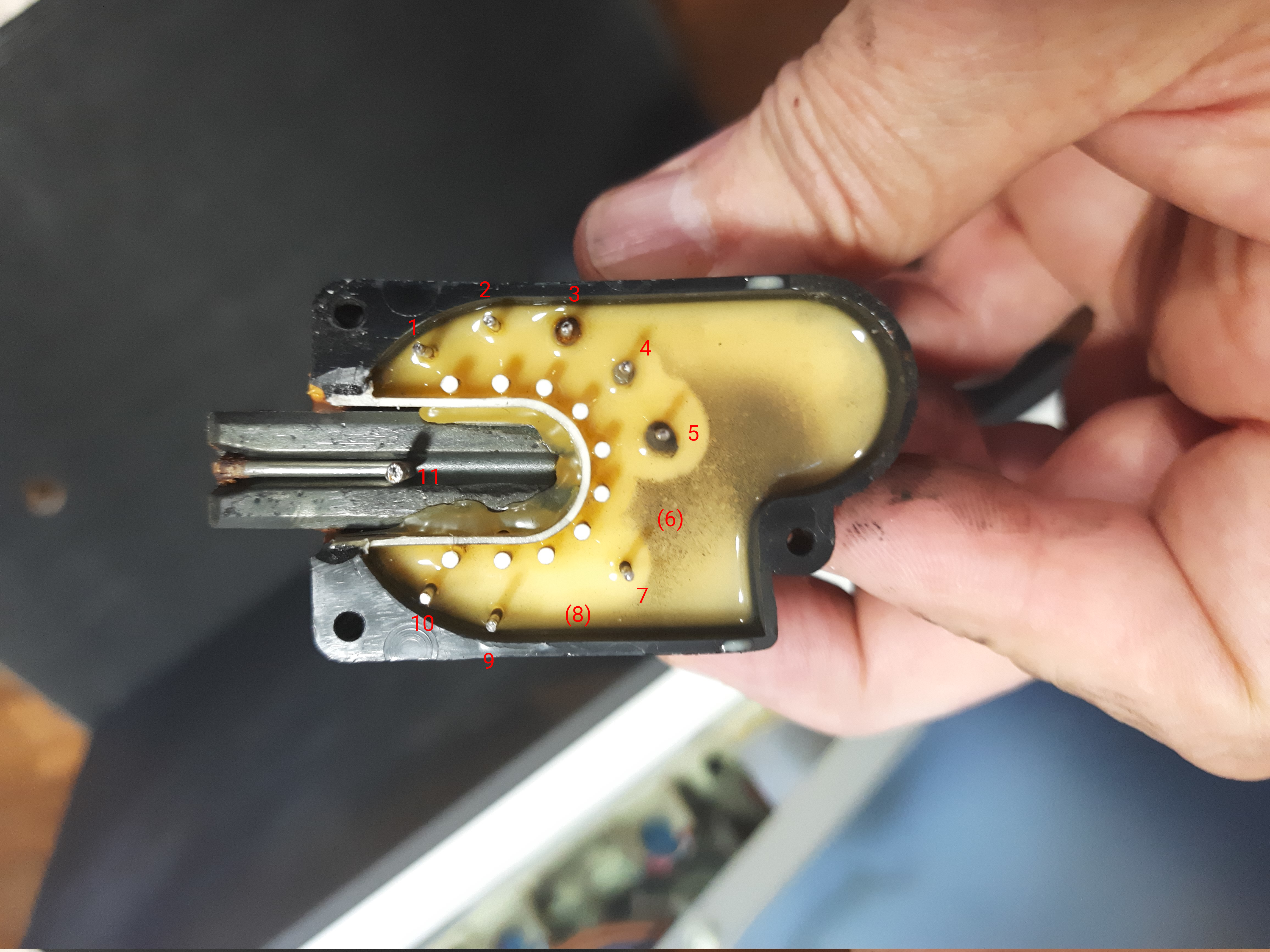
- My pin numbering may differ from the official pin numbering
- Pin 2 is not connected.
- Pin 5 is high voltage coil ground
- Primary coil 1 is between Pin 1 and 4
- Primary coil 2 is at Pins 3,7,9,10
In total, I checked at this first step these parts:
- T601 SAMPO FDA001A Flyback Transformer HV measured, may be ok, maybe not.
- Q600 BU406 NPN Power Trans. HV ok
- Q801 IRFPE40 Power MOSFET PSU ok
- C804 220u/400V Capacitor PSU ok
- D802 Power Diode PSU ok
- D606 BY548 HV diode 1500V HV ok
- C805 220u/35V Capacitor PSU looks burned, 110u left. Changed it.
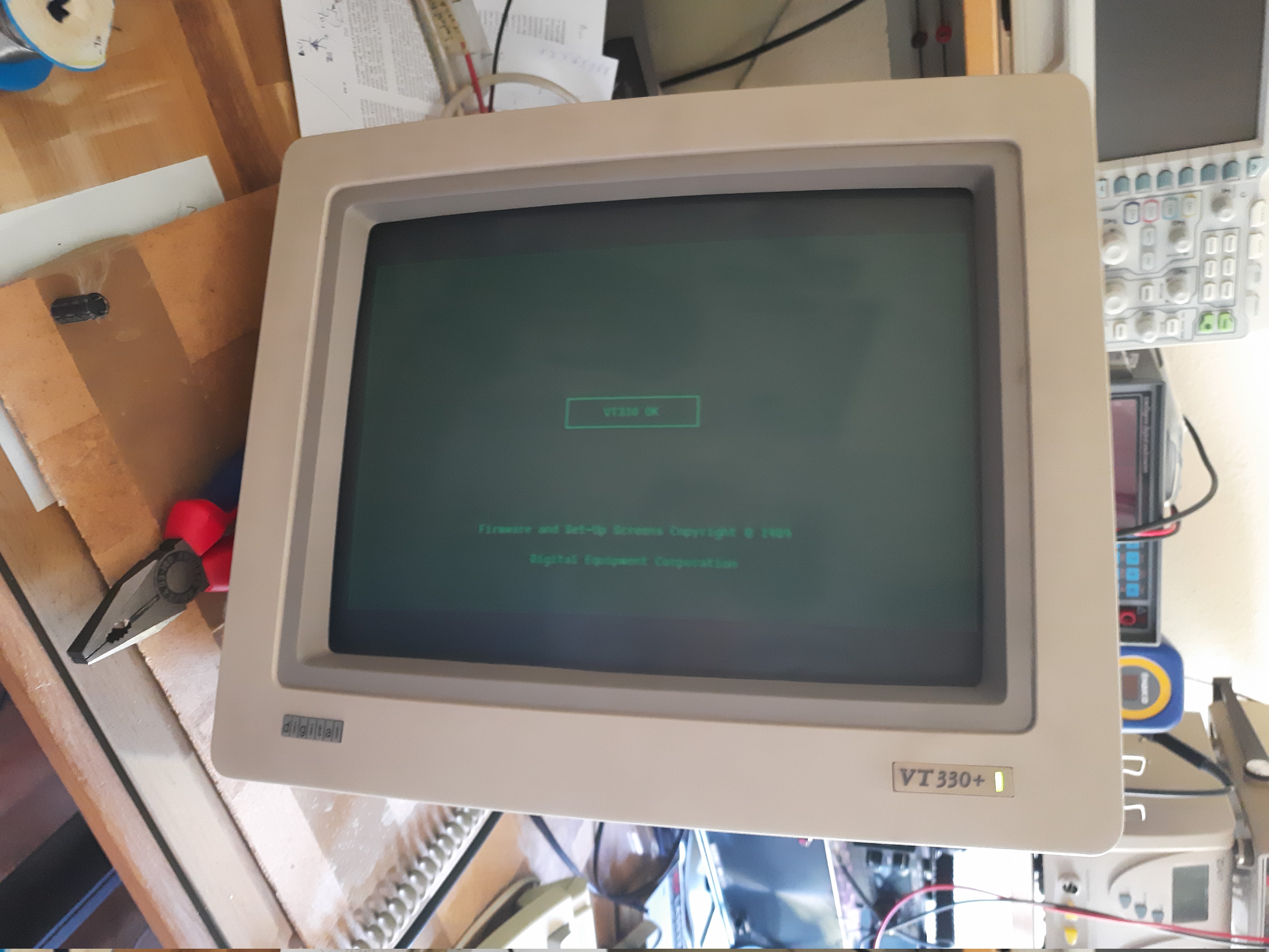
Finally, I found a broken part, C805. I put everything back together and gave it a try. And tada… somehow the CRT came up. I have an unused LK401 keyboard that fits well to the VT330+.
First sign of life from the terminal, very dim and unfocused:
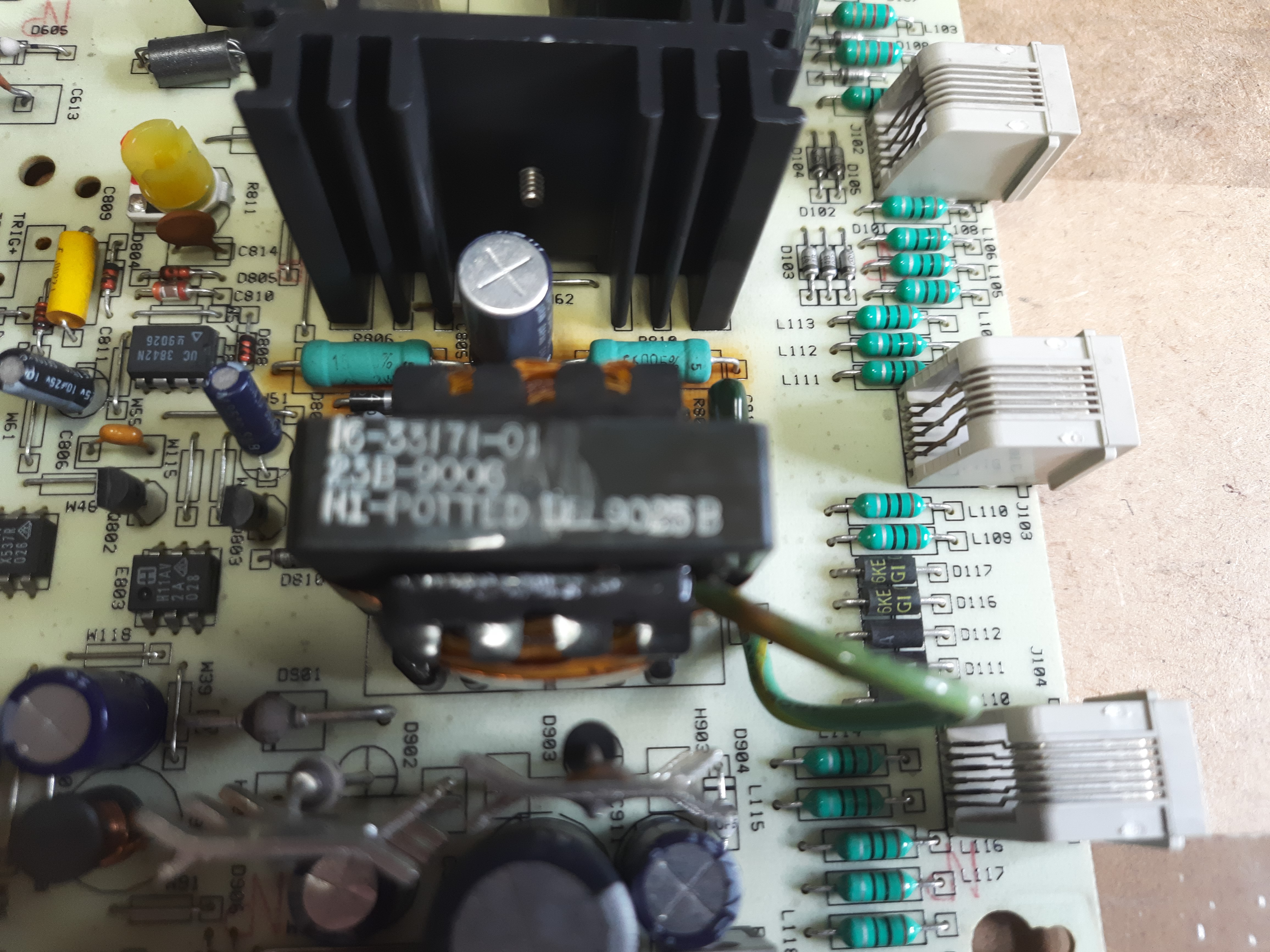
Next image shows defective C805. This seems to be a very hot area, look at the
browned PCB. For sure the capacitor went to hot for a long time and lost
capacity.
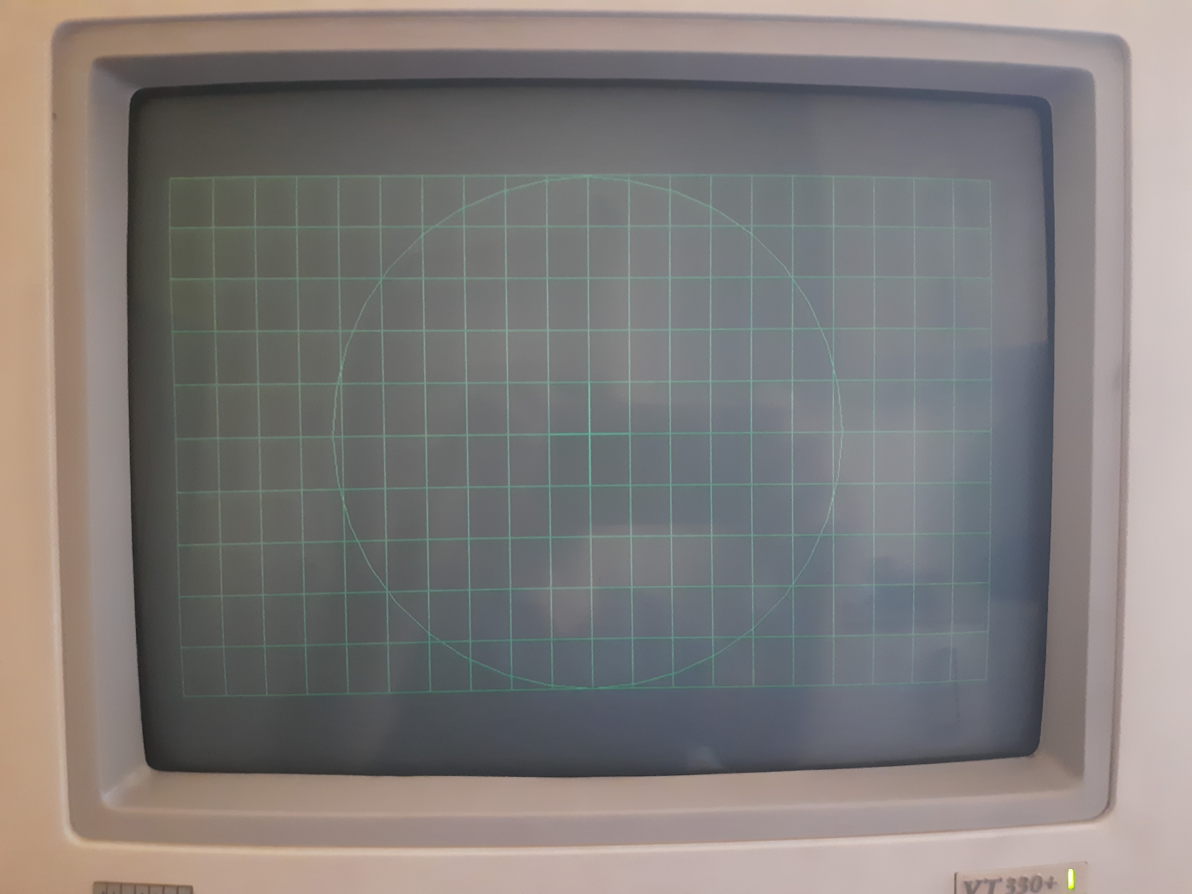
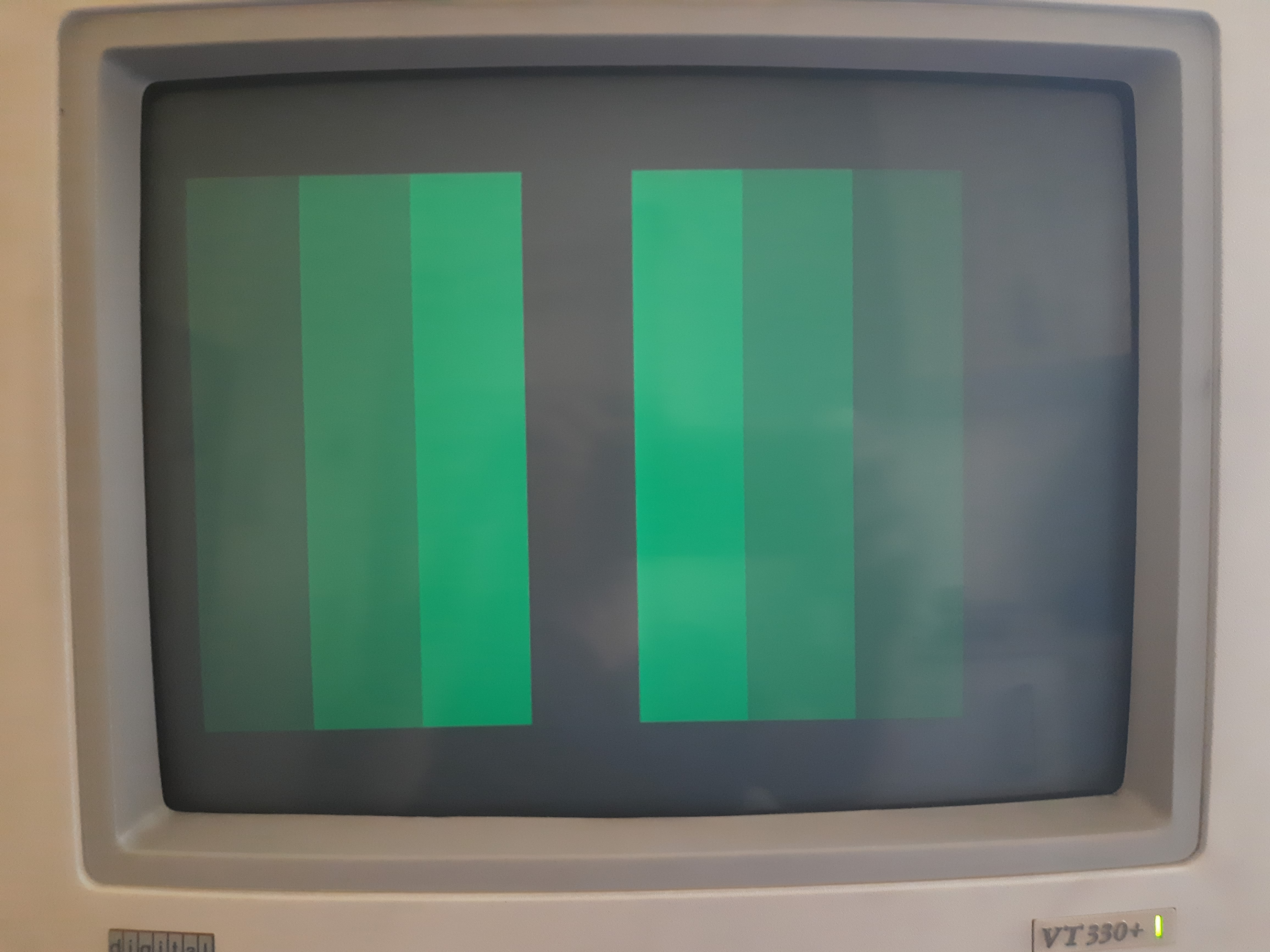
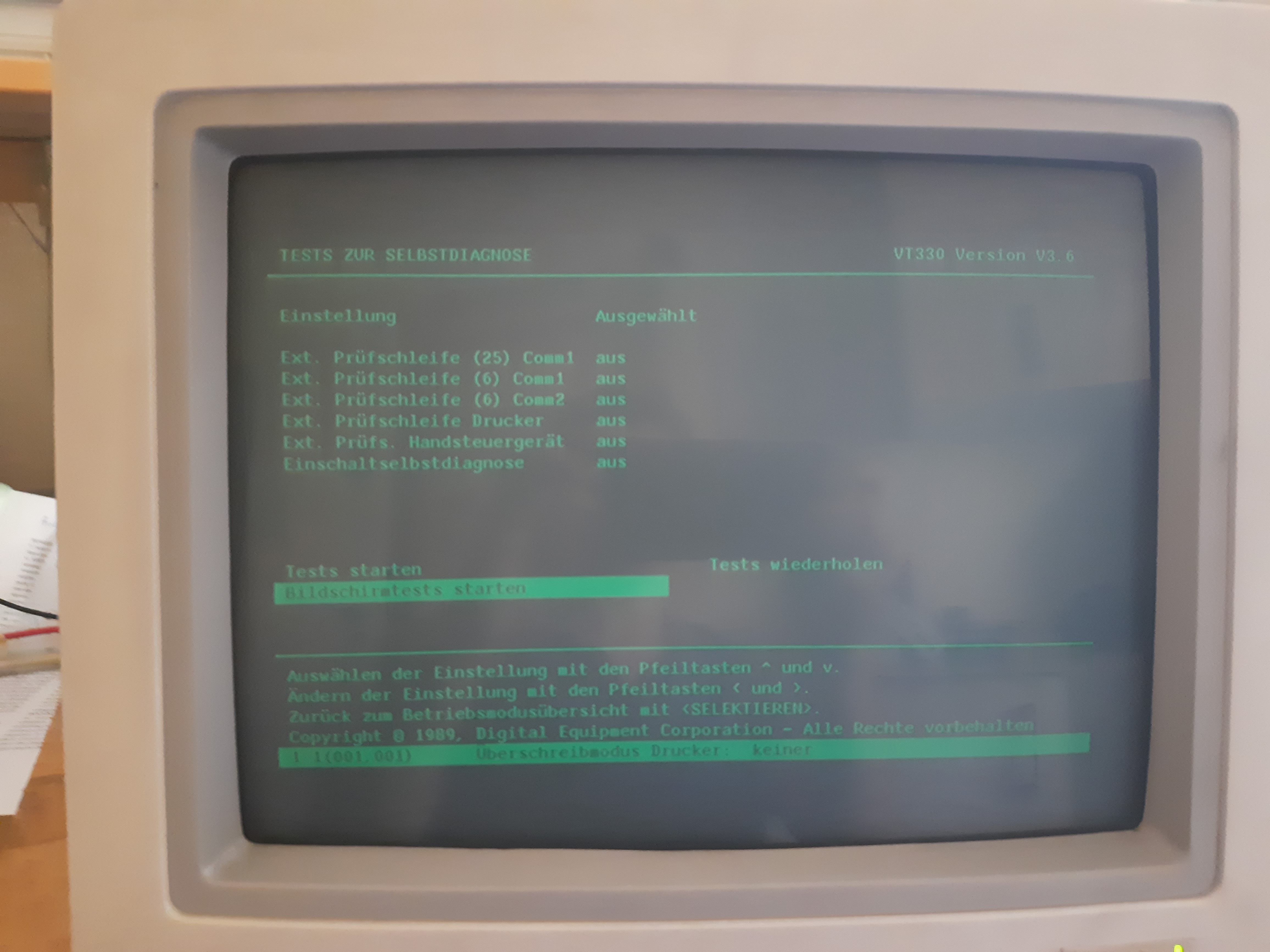
After playing around with video controls, I had a better image, but still not bright enough. Next three images show some built in display self test images:
Next I focused on two issues:
- The monitor does require several switch ons to really start. I can hear some repeated noise inside, it looks like the power supply does oscillate somehow. Maybe another broken capacitor.
- Missing brightness. From short check in Internet, either the tube has aged too much or the high voltage is too low.
My hope was that the poor brightness is related to some PSU weakness, so I started with the first issue. The tube shows no traces of aging, no burned in characters and such. So I hope aging is not an issue.
In a second repair session, I checked many parts around the UC3842, the main chip in power supply area. Because there is no schematics, it is not easy to do this.
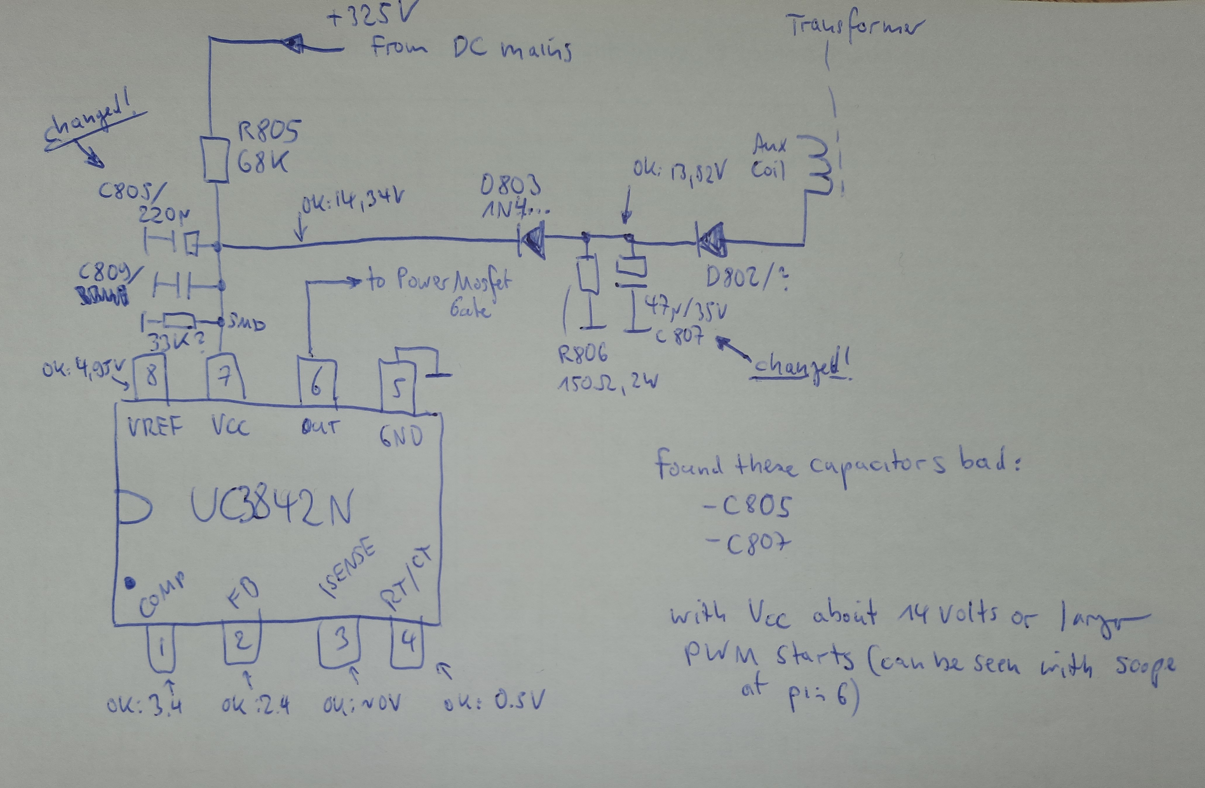
I tried to reverse engineer the schematics around UC3842, see next image.
“Transformer” is flyback transformer. “Changed!” means, these capacitors lost
capacity over time. “ok” means , these DC values were measured when vt330+
was working ok and displaying an image.
Checking that area is also risky, because the flyback transformer emits about 15 kilovolts, and even the primary side of this transformer may have voltages that are deadly. So each step needs to be done very very carefully. I recommend not to do it if not being an educated TV servician.
I checked various capacitors (C704,904,908) which all look ok, from capacity value side and from ESR side. Also, diodes D802 (again) and D803. Also, the resistors that provide supply voltage during startup to UC3842, and later, these are R806,810,805. During startup, the power comes via R805 directly from 325 volts DC mains supply. C805 cleans DC then. After startup, the power comes from an auxiliary coil of the transformer, via diode D802 and D803. C807 cleans the DC in that case.
I found that C807 has a nominal value of 47µF, but tested with a capacitor tester at 1Khz it has only 24µF left. So I exchanged this.
When testing around, I also killed the UC3842, when creating a short between some of its pins. So I soldered in a IC socket and put in a new UC3842.
After this, I put everything together and tried. I had luck, and it came out that that capacitor change fixed the issue with the repeated failing starts. The terminal now comes up always on first switch on.
Alas, the brightness did not improve. Because the tube seems not over-aged, this may be an issue with the high voltage at display tube to low. I ordered a 50KV high voltage probe and will do some measurements when it is arriving.
Checking HV voltage
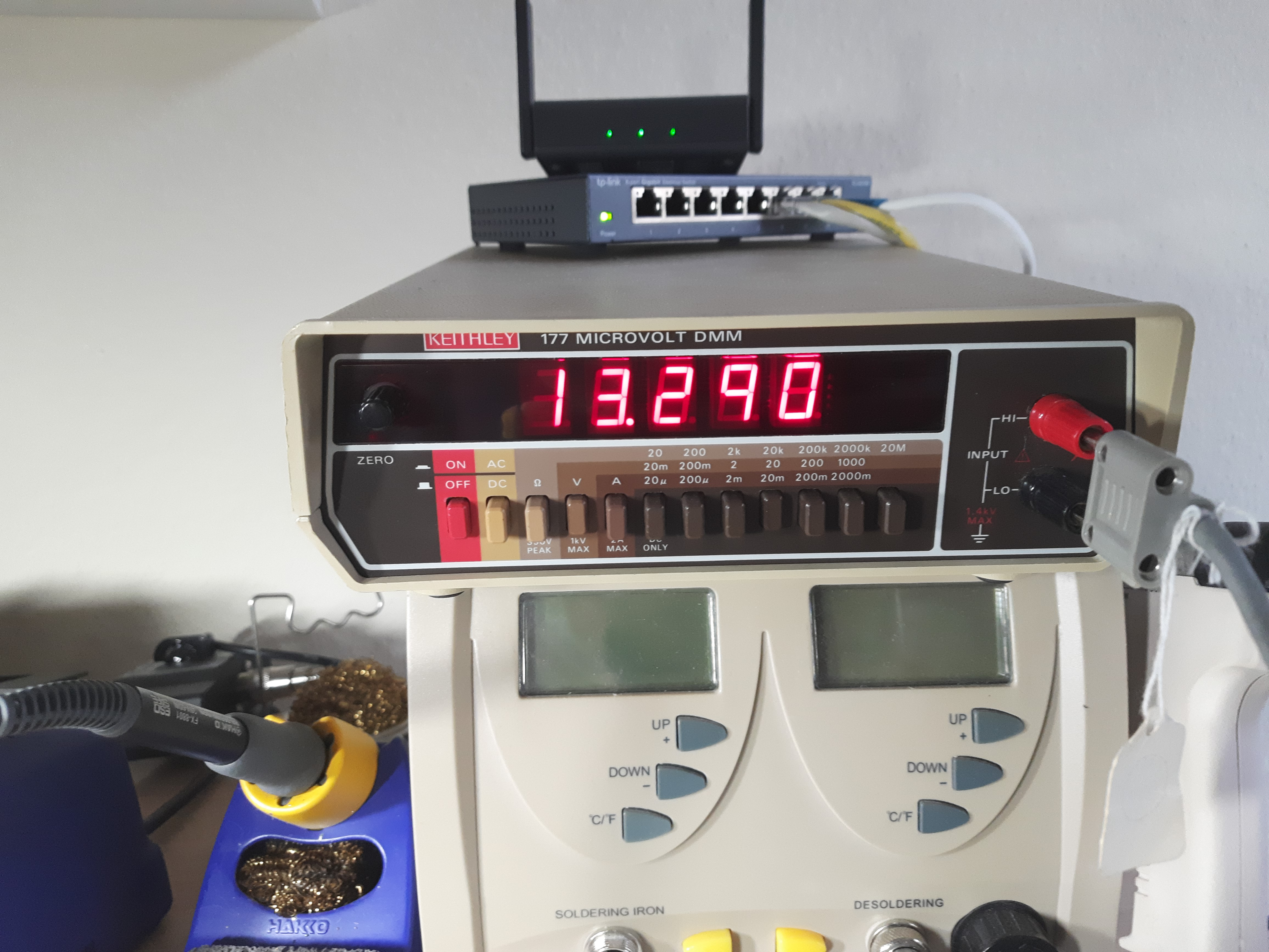
After my Beckman 50KV HV-211 probe arrived from some military complex surplus in Albuquerque, New Mexico, I was able to measure high voltage at anode of VT330+. I measured 13.1 KV at anode tip.
Next image shows the HV probe, applied to anode tip of another terminal (vt420).
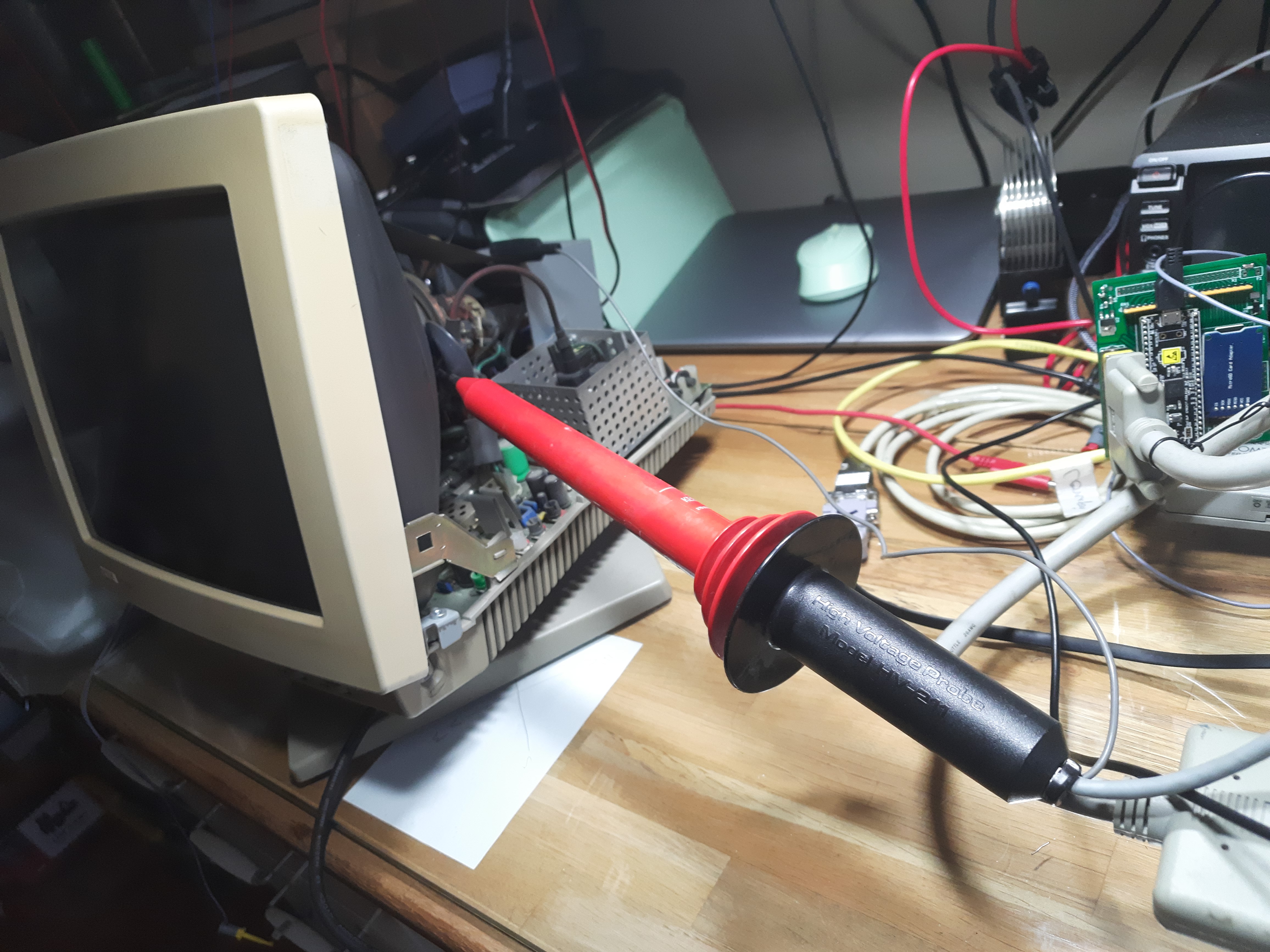
Readout on a DMM. “13.290” volts is actual voltage at probe tip, divided by 1000.
So this is 13290 volts.
Because I have no schematics with valid data for anode voltage, I cannot decide if 13.1KV is too low or not.
I hoped for measuring a value of 8 or 9KV, that would be too low for sure…
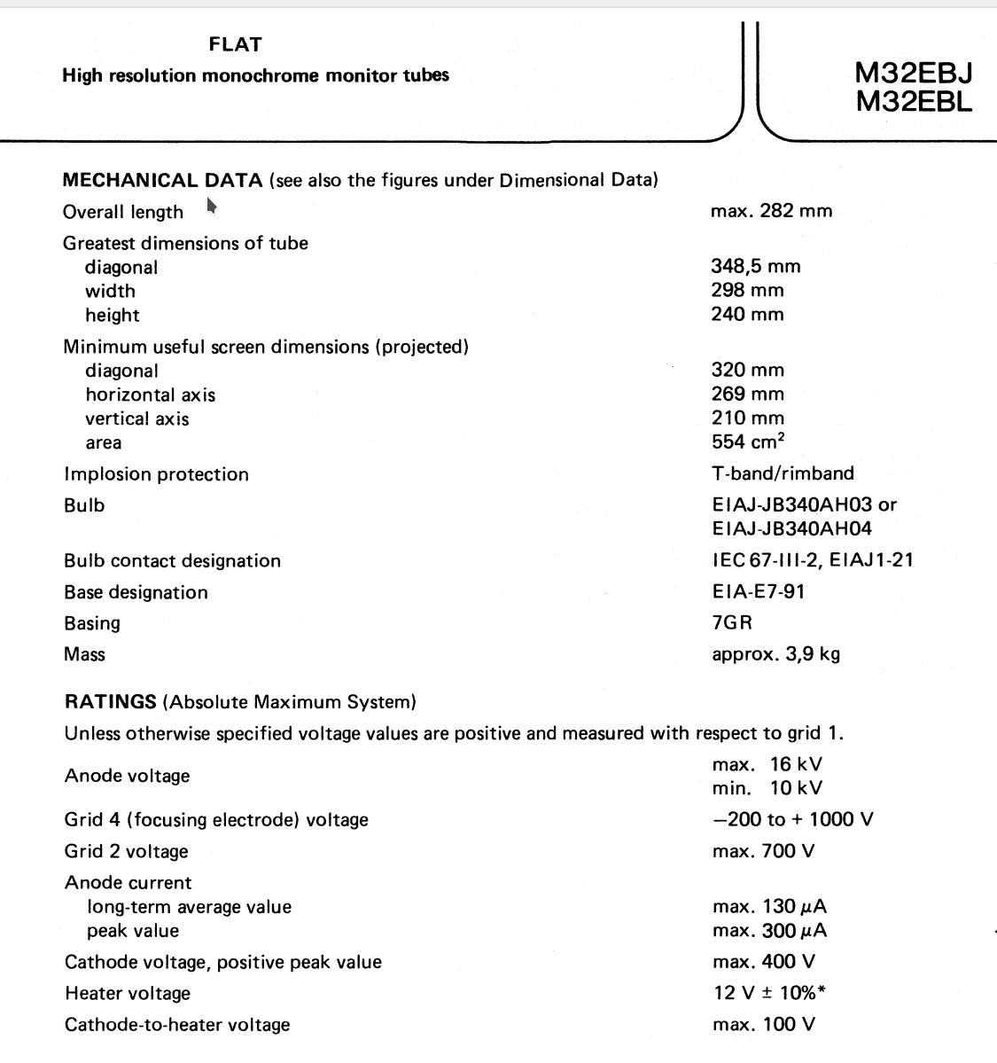
Tube is a 14 inch diameter Philips M32EBL12GH. For Philips tubes, I found an old document (named “Phi89-dc02.pdf”). This lists 14KV as nominal value. Absolute maximum values are 10-16KV. So 13.1KV may be ok, but its 900 volts below the nominal value listed by Philips.
The “G” in M32EBL12GH stands for green, btw.
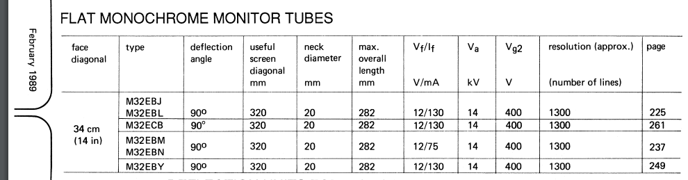
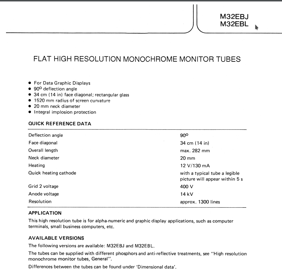
Typical operating values:
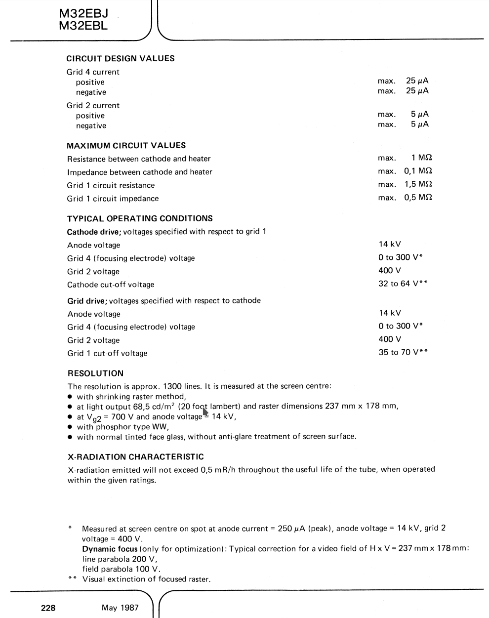
Absolute maximum values:
Comparison to VT420 HV voltage
I have also a well working VT420 (see here ), also 14 inch diameter. I measured there 13.2KV. The tube there is a Philips M32EBY114WRB. The “W” in M32EBY114WRB stands for white.
This tube has same electric values from datasheet (14KV nominal, 10-16KV maximum ratings) and same diameter. It is obviously driven by 13.2KV and gives a good bright display.
So I would say, 13.1KV for the VT330+ is not too low.
Maybe the brightness is influenced by some other tube control. Have to reseach on that next.